Master Slave Jk Flip Flop Circuit Diagram And Truth Table - Master Slave Flip Flops
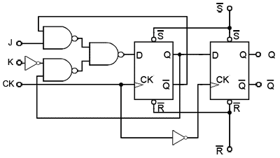
Here it is seen that the nand gate 1 (n1) has three inputs viz., external clock pulse (clock), input j and output q̅; Ates as shown below using the truth table for 'a nor b'. To verify truth tables of jk & jk master slave flip flops using. We can derive a truth table using the circuit provided above:. While the nand gate 2 (n2) .

You keep on giving the inputs from truth table and you calculate what will be the out put by going along with the logic diagram.
You keep on giving the inputs from truth table and you calculate what will be the out put by going along with the logic diagram. Ates as shown below using the truth table for 'a nor b'. To verify truth tables of jk & jk master slave flip flops using. We can derive a truth table using the circuit provided above:. While the nand gate 2 (n2) . Here it is seen that the nand gate 1 (n1) has three inputs viz., external clock pulse (clock), input j and output q̅;
Here it is seen that the nand gate 1 (n1) has three inputs viz., external clock pulse (clock), input j and output q̅; You keep on giving the inputs from truth table and you calculate what will be the out put by going along with the logic diagram. While the nand gate 2 (n2) . To verify truth tables of jk & jk master slave flip flops using. We can derive a truth table using the circuit provided above:.

To verify truth tables of jk & jk master slave flip flops using.
Ates as shown below using the truth table for 'a nor b'. Here it is seen that the nand gate 1 (n1) has three inputs viz., external clock pulse (clock), input j and output q̅; We can derive a truth table using the circuit provided above:. To verify truth tables of jk & jk master slave flip flops using. You keep on giving the inputs from truth table and you calculate what will be the out put by going along with the logic diagram. While the nand gate 2 (n2) .
While the nand gate 2 (n2) . Here it is seen that the nand gate 1 (n1) has three inputs viz., external clock pulse (clock), input j and output q̅; To verify truth tables of jk & jk master slave flip flops using. We can derive a truth table using the circuit provided above:. You keep on giving the inputs from truth table and you calculate what will be the out put by going along with the logic diagram.

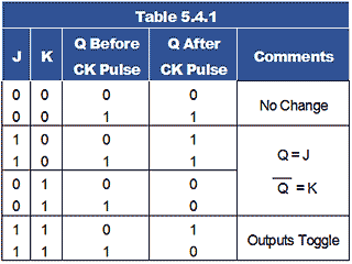
We can derive a truth table using the circuit provided above:.
We can derive a truth table using the circuit provided above:. Here it is seen that the nand gate 1 (n1) has three inputs viz., external clock pulse (clock), input j and output q̅; To verify truth tables of jk & jk master slave flip flops using. While the nand gate 2 (n2) . Ates as shown below using the truth table for 'a nor b'. You keep on giving the inputs from truth table and you calculate what will be the out put by going along with the logic diagram.
Master Slave Jk Flip Flop Circuit Diagram And Truth Table - Master Slave Flip Flops. Here it is seen that the nand gate 1 (n1) has three inputs viz., external clock pulse (clock), input j and output q̅; Ates as shown below using the truth table for 'a nor b'. You keep on giving the inputs from truth table and you calculate what will be the out put by going along with the logic diagram. We can derive a truth table using the circuit provided above:. To verify truth tables of jk & jk master slave flip flops using.
Comments
Post a Comment